An arc fault in a solar system occurs when an electrical current jumps across a gap between two conductive surfaces, creating a brief but intense burst of heat and light. This can happen when there is damage or wear to electrical wiring, connectors, or other components in a solar PV system, creating a pathway for the current to arc.
Arc faults can be dangerous because they can start fires, damage equipment, and cause system failures. In addition, they can be difficult to detect because they often occur in areas that are not visible or accessible.
To address this issue, many modern solar systems include arc fault detection devices (AFDDs) that monitor the system for signs of arcing and can automatically shut down the system if a fault is detected. These devices help to improve the safety and reliability of solar PV systems. Along with AFDDs there has to be An AFCI or Arc Fault Circuit Interrupter. An AFCI or Arc Fault Circuit Interrupter is a device used to detect arcing in an electrical circuit and to interrupt the flow of current. It is installed in many types of electrical circuits to reduce the chances of an electrical fire due to faulty wiring, bad wiring connections or damage sustained during wiring installation.
Possible Arc Fault Causes:
●Connections in junction boxes can degrade (oxidize) over time creating hot spots.
●Screw type terminal connections can come loose due to changes in temperature.
●Improper stripping length can result in wire insulation being captured in terminals.
●Improper crimping of DC terminals results loose connections and arcing.
●Improper connector assembly results in connection not being "locked" and arcing.
●DC connectors not fully mated causes arcing.
●Animals chewing through wires or wiring that has come loose and rubbed against the array racking can also lead to serial arcing.
●PV Panels are cracked or damaged.
●Firmware is out of date
●AFCI Board is damaged or connection to DSP is damaged
Detection of Arc Fault Causes:
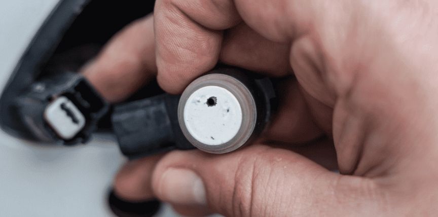
Most of these are common conditions and easily identified with a quick visual inspection. First of all, arcing leaves some evidence. The may be discoloration of wiring and racking, melted connectors and insulation or even burned junction boxes on the back of panels. A quick visual inspection can locate such issues very reliably. A gentle tug on DC cables whether in the home run connections, panel to panel connections or in the combiner/wiring box can locate wires that have loosed or were not terminated properly. The below picture is an example of improperly terminated DC connections in a wire box and blindly resetting an Arc Fault without verifying all DC connections. The DC circuit includes all connections, even those in the inverter.
Another method to locate arc fault issues is somewhat easier to execute, but does not pinpoint the issue to a specific connection and the results can be difficult to interpret.. For rooftop installations, it may not be easy or even possible to perform the above visual and manual inspection. In these cases, it is recommended to use some sort of high voltage tester to test the cabling to locate a failure. A “Megger” or megohm meter is one example of a simple test set that can help locate arcs to a specific string. For more testing functionality, a string tester is preferred because it can detect not only serial arcs, but also insulation issues and ground faults in the DC cabling. While it is considerably more expensive, it is far more flexible than the simple “megger” and can be useful in troubleshooting other array issues.
Both of these devices usually test at 250V, 500V and 1000V. Neither test at 600V which is what residential and some small commercial systems are rated at for maximum VOC. If the PV and DC wiring is only rated at 600V, use the 500V setting to test. If the system uses panels and cable rated at 1000V, even if it is residential, it is suggested to test at 1000V. The reasoning is simple; a fault may only occur at voltages higher than 500V on cold bright days in a 600V system. The test may pass at 500V, but can fail at 1000V. When using the megger, a failure indication is a resistance that is higher than "nominal zero". A 'nominal zero' will not be zero ohms, but the baseline resistance that was recorded during the system commissioning tests. Once the faulty string is isolated, then the first method can be used to locate the faulty component.
A final method that can be used is to measure the temperature of the connectors, terminals and junction boxes using an infrared thermometer. These thermometers are quite cheap and effective; they can be purchased from any big box home improvement store. Typically, a connection that has a significantly higher temperature than like connections has a higher resistance and may be causing arc faults. When measuring the temperature of the connections, take into account the location of the connection; a connection that is in direct sunlight may read a higher temperature than one underneath PV panels.
If after all these tests no defect is found, then it is safe to assume that a “false” or nuisance trip has occurred. In this case, reset the fault and observe the inverter to see if it immediately faults again. If so, The AFCI circuit may be faulty and the inverter needs replacement. If not, try to record the exact conditions when the arc fault occurs. It may not be a sensitivity issue, but a weather related issue. Check local weather to see if there were any special conditions that may have contributed to the suspected “false” trip.
A simple rain storm can also uncover issues on a system including arc faults that only occurs when the wiring is wet. Finally, report any findings back to the inverter manufacturer. You input is very valuable in the continued refinement of equipment. A manufacturer tests to many conditions to cause a failure, but nothing can completely replicate the conditions on your sites in the real world.
How to deal with Arc Faults:
Here are some steps you can take to deal with an arc fault in a solar system:
Shut off the system: The first step to dealing with an arc fault is to shut off the solar system to prevent any further damage or risk of injury. Turn off the circuit breaker or disconnect switch that supplies power to the system.
Locate the fault: Use a thermal imaging camera or other diagnostic tools to locate the fault. The thermal imaging camera can detect hot spots where an arc fault is occurring.
Inspect the wiring: Once you have located the fault, visually inspect the wiring and components for any damage or signs of overheating. Look for loose connections, frayed wires, or any other visible signs of damage.
Repair or replace damaged components: If you find any damaged components, repair or replace them as necessary. This may involve replacing a damaged wire, tightening a loose connection, or replacing a damaged component such as a fuse or circuit breaker.
Test the system: After making any necessary repairs or replacements, test the system to ensure that the arc fault has been eliminated. Turn the system back on and monitor it for any signs of overheating or other issues.
Seek professional help: If you are not comfortable working with electrical systems or if you are unable to locate or repair the arc fault, seek professional help from a licensed electrician or solar installer. They can help you diagnose and repair the problem safely and effectively.
Products and reference designs of Solar arc protection
Input current sense
This system is required to accurately detect current flow from load terminals with a resistive or magnetic current sensor. Isolation may be applied. Input current sense includes General-purpose op amps、Precision op amps (Vos<1mV)、Comparators、Isolated amplifiers, the corresponding products are TLV9152、SM73307、LM2901、AMC1301
Ground current sense
A second current sensor stage is needed to predictively detect slowly developing insulation breakdown. That information is also fed into the logic system after being conditioned. Ground current sense includes General-purpose op amps、Precision op amps (Vos<1mV)、Comparators, the corresponding products are TLV9152、TLV9152、LM2903
Relay control power stage
In order to enable a circuit breaker, the system should contain a relay with an appropriate driver. Relay control power stage includes Solenoid drivers、N-channel MOSFETs, the corresponding products are DRV110、CSD18531Q5A、CSD17571Q2
Test circuit
With this feature, the system function can be tested. As soon as the user pushes a button, a signal similar to an arc is generated and inserted into the signal chain. If the solar arc detection is working correctly, the circuit breaks. Test circuit includes General-purpose op amps、Precision op amps (Vos<1mV), the corresponding products are TLV9004、LMP7716
Logic
Communication between the processor and various interfaces often need different logic levels and might require a level shifter or translator. Logic includes Inverting buffers & drivers、Noninverting buffers & drivers, the corresponding products are SN74LVC1G04、SN74LVC2G07
Signal isolation
Communication between the processor and various interfaces should be functionally isolated to help ensure immunity against common mode transients. Signal isolation includes Digital isolators、Isolated CAN transceivers、ESD protection diodes、TVS diodes, the corresponding products are ISO7840、ISO1050、TPD1E10B06、TVS3300
Wired interface
To make the conditions understandable for the user or other external devices, transceivers for common industrial interfaces like RS-485 or Ethernet should be included. Wired interface includes RS-485 & RS-422 transceivers、RS-232 transceivers、Isolated CAN transceivers, the corresponding products are SN65HVD82、TRS3243E、ISO1050
Self-diagnostics/monitoring
Overheat protection can be implemented into the system. Self-diagnostics/monitoring includes Analog temperature sensors、Digital temperature sensors, the corresponding products are TMP235、TMP116
Analog front end
The output of the current sensor runs through a filter that passes frequency components of arcing waveforms and blocking all other frequencies. After conditioning the signal, it is guided to a logic circuit. Analog front end includes Precision op amps (Vos<1mV)、General-purpose op amps、Isolated amplifiers、Precision ADCs, the corresponding products are SM73307、TLC2272A、OPA4323、AMC1301、SM73201
Digital processing
The power stages in the solar arc protection system are controlled by a MCU. It determines if an unwanted condition exists. Amplitude and duration are used to calculate an arcing condition. If a condition is detected, a signal is sent to open the relay and break the circuit. It also converts the signals given from the current sense stage and brings it to the user by various interfaces. Digital processing includes C2000 real-time microcontrollers、MSP430 microcontrollers, the corresponding products are TMS320F28P650DK、TMS320F280049、MSP430FR2533
Output user interface
The interaction between the user and the system must be easy to use and understand. These requirements can be achieved through the use of displays and LEDs. With the output interface, the end user can quickly and easily monitor the solar arc protection system. Output user interface includes LCD & OLED display power & drivers、ESD protection diodes、TVS diodes, the corresponding products are TPS65130、TPD1E10B06、TVS0500
Input user interface
Capacitive, inductive or functions with haptic feedback can be easily implemented. In this way, the user can recall error states. Input user interface includes Signal conditioners、MSP430 microcontrollers, the corresponding products are DRV421、MSP430FR2633
Wireless interface
A wireless communication option will enable remote monitoring and control of the protection box. Wireless interface includes Wi-Fi products、Sub-1 GHz wireless MCUs, the corresponding products are CC3220S、CC1312R
Isolated DC/DC power supply
A solar arc protection may have many different voltage domains. Some are hundreds of volts above others. For each isolation domain, a dedicated power supply is required to ensure the high side sensing electronics have stable power and enough to drive high current FET gates, in some cases. Isolated DC/DC power supply includes Buck modules (integrated inductor)、Isolated DC/DC converters & modules, the corresponding products are TPSM63602、LM5160
Non-isolated DC/DC power supply
The internal electronics of a solar arc protection system require a number of separate voltage rails. MCUs and other digital controllers will typically run at 3.3V////; however, some digital processors operate at voltages like 1.2V. Non-isolated DC/DC power supply includes Buck converters (integrated switch)、Linear & low-dropout (LDO) regulators、Supervisor & reset ICs、Charge pumps (inductorless), the corresponding products are TPS62441、TLV757P、TPS3897、LM2776
Power monitoring
To ensure all the different rails give the correct value, an optional supervisory socket can be added. Power monitoring includes Supervisor & reset ICs、General-purpose op amps、Comparators, the corresponding products are TPS3828、OPA4323、TLV9062、LM2901
In general, it's important to regularly inspect and maintain your solar system to prevent arc faults and other potential hazards. Regular maintenance can help ensure the safe and reliable operation of your solar system for years to come.
Previous: Electric power steering (EPS)